Pixinsight-Part 1 (Blink & SubFrame)
After using Photoshop for some years I always had this urge to try Pixinsight, as I always say, you learn something new everyday, and who knows I might develop my processing and advance further, I am not sure where I am going or what I will achieve, but whatever I lean or not I will recorded each step on the way.
When I open SI and I see all the different processing tools under 'All Process' and those under 'Scrip' and the first impression is wow, where do I start??, while in Photoshop, the frames are coming over already calibrated (from third party software like PhotoStack2), in SI you have the option to do the calibration as well, or used a third party software to carryout this task and just concentrate on the processing the frame in PI, so this addition of extra menus its a bit intimating.
.
First before I start this adventure I will start off by describing the meaning of 'Image Scale' followed by some useful points about PI , why?, because this awareness will come handy later.
1. Image Scale
arcsec/pix=(pix size/focal length)*206.3
Is the angular area of each pixel can see, this is referred as 1 bin, so if we combine 4 pixels into a single pixel the are will increase by 4x = 2bin.
First Setup
A camera / telescope combination. Telescope with 106mm aperture and 530 focal length, this means a F5 (530/106). The camera chip 2750 x 2200 with 4.54 pixel size. The image scale of the pixel is 1.76 arcsecond/pixel and the field of view is of 80.98 x 64.79 arcmin
Second Setup
Telescope 356mm FL is 2563mm therefore F7.2 will result of an Image Scale of 0.72 arcsec/pixel and Field of View of 48 x 33 arcmin with an FOV in degrees of 0.8.
So the best resolution of both combo is the latter with a 0.72 arcsec/pixel
2. Loading an Image
When loading an image in PI in 32 bits, the computer will display it in 8 bits, do not reduce from 32bits to 8bit the images. Instead use the STF (Screen Transfer Function) to stretch the images to see it better on the computer screen.
3. PI is divided into two main sections for processing.
On one side we have the Process and on the other the Scrip. In Process you can find all the tools provided by PI, and in Scrip are third parties software within PI developed by PI users.
4. On the top screen modules/menus
On the top selections we have : File-Edit-View-Preview-Mask-Process-Script-Workspace-Window-Resources and if you scroll down there are quite a bit of extra menus.
We will skip these menus for now.
5. Inside PI (whole)
The software is divided into 4 sections - Preprocessing, Linear Post Preprocessing, Nonlinear Post-processing and Special Processing
Part 1
Pre-Processing
The processing of an image can be achieved by using the processing tools, if you click on the 'Process' and then <all process> you will open the screen below.
After a night of imaging you are exacting but also aware that not all the frames would be use for calibration for different reasons, previewing them can be achieved in PixInsight. Most processes can take quite a bit of trial and error to get the right settings and fine tune them for the optimal result. We run these processes on previews so that it is much faster to see the effects compared to running it on the complete picture. Furthermore, we can use multiple copies of the same preview and apply the process with different settings so we can really compare the results of our fine tuning in great detail.
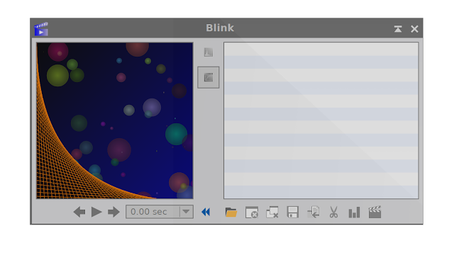
One of tools that unable preview your frames is 'Blink', it will preview a set of images. Open the images with the small folder in the Blink dialog window.

This tool will be part my of image-processing workflow, which lets me inspect each image and discard any that appear to
be of poor quality (images with clouds, poor tracking, and so on). PixInsight’s
SubframeSelector script (Script > Batch Processing > SubframeSelector)
can automatically evaluate images and sort them into “approved” or “rejected”
groups using quality criteria you can modify. When evaluating image quality, I will use this opportunity to identify the best one to use as a reference when
aligning images.
Preselection frames
1. Open the Blink tool
in the Process Explorer (vertical tabs);
2. Select the light
subs in the Blink tool;
3. Press the "play"
button and check if you see streaks of satellites, planes or meteorites;
4. If stripe formation is
visible, it is usually located in one subframe, write down the name of the sub
in order to have it removed in the subsequent steps or remove all the file
physically by
removing the 'X' to mark it as bad.
removing the 'X' to mark it as bad.
5. Its important that you keep those good-looking images and have adequate number of good images.
6. Thinking about those poor images, I believe it will be a good idea to create a new folder (give it a name that you know they junk images).
6. Thinking about those poor images, I believe it will be a good idea to create a new folder (give it a name that you know they junk images).
The following Video will help you to understand better the process
SubframeSelector script
After calibrating we could immediately
jump to registration (aligning the images). However, there’s another tool
in the PixInsight called SubframeSelector that can help to enhance your
results if we use it before registering our data. The
originatly the SubframeSelector was to identify light frames that
might have errors that were severe enough to exclude
them in your final stack. This could be from a cloud passing through the
field of view, a piece of grit sticking in your gears and throwing off your
tracking, focus slipping, etc. It also supports the ability to add a
keyword into the FITs header that can be used by ImageIntegration later on to
weight how the images are combined (but this is another story). This is exceptionally useful if you
have data from multiple sessions or instruments where the SNR or resolution my
vary considerably due again to the elements mentioned above. By weighting images you can control how much influence
an sub frame with a lower SNR has on the final integrated image.
First step is to select the images then move to opening it inside SFS (see below), Under System Parameters, enter the image scale
of your telescope (use the formula I mentioned above) and camera in arcseconds per pixel and other pertinent
information.
If your are setting the Star Detection and Fitting and these settings are inadequate, the console will report failure, leave the setting as default it works perfectly, but before hitting the measure button, if you feel that you can enter a formula into Expressions/Approval to automate the grading process, do so, if not do not worry. Finally click measure, and the Process Console will appear as the script does its calculations.
Tables
The Table at the bottom , shows the finding calculation Note, you can change the field of
interest, three of the main and basically used by many astrophotography are: the images’ signal to noise ratios
, choose SNRWeight (noise), and in descending, if the SNR reading is higher-this is a good thing.
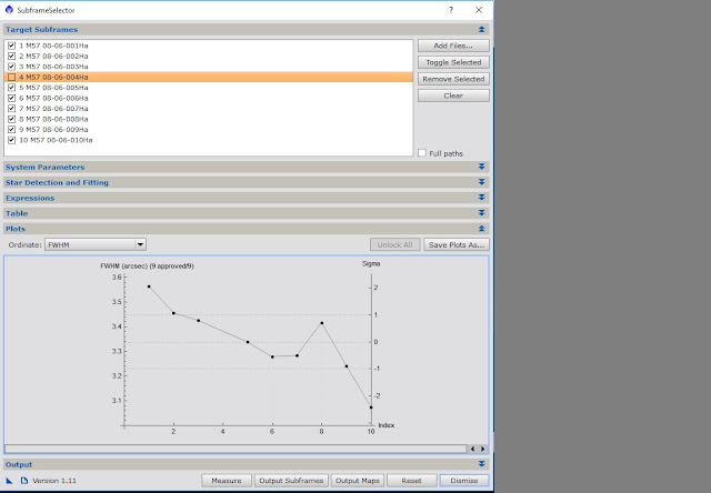
If your choose on the Full Width at Half Maximum (FWHM) of the stars in the images, remember if the file at the top of the list would have the highest FWHM value—this is a bad thing. You might therefore switch to ascending order, placing the file with the smallest/best FWHM on top to make that category easier to read.
Formula into Expressions/Approval
Limits -Minimum and Maximum settings
For eccentricity <=0.4 is considered 'round', if anything from 0.4 to 0.49 will be acceptable, if generally stack anything <0.55 and above 0.55 and start to get picky and choose, it all depends how many frames you have to play with. For example if they're mostly 0.4 to 0.5 you can select with assurance and toss away any outliers that are above that, I would reject anything above 0.6.
FWHM is a lot harder to be so absolute about, as it largely a factor of the seeing. On a really good night a seeing <3", but a 5" is considered poor. As such, for FWHM I tend to work in relative terms within the available frames I have for a target rather than absolutes. FWHMSigma is a good approval term to use for this and I'll typical approve frames that lie within 2 sigma, so an approval term of FWHMSigma < 2.
To sum up a typical approval expression I'll use for these factors in SubframeSelector will be:
Eccentricity < 0.5 && FWHMSigma < 2
[What I am saying here is I will only accept those frames with FWHS that lies with 2" and Eccentricity with a 0.5 value or below, any frame above any of these two parameters will be automatically rejected.]
If your choose on the Full Width at Half Maximum (FWHM) of the stars in the images, remember if the file at the top of the list would have the highest FWHM value—this is a bad thing. You might therefore switch to ascending order, placing the file with the smallest/best FWHM on top to make that category easier to read.
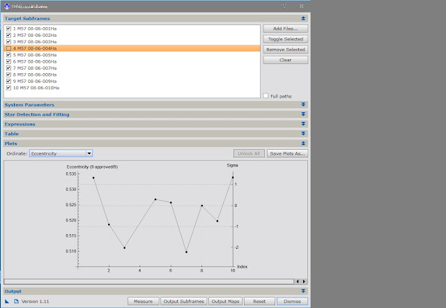
FWHM measures star size/spread whereas eccentricity
measures shape in terms of how out of round the star are.
Formula into Expressions/Approval
Limits -Minimum and Maximum settings
Eccentricity
For eccentricity <=0.4 is considered 'round', if anything from 0.4 to 0.49 will be acceptable, if generally stack anything <0.55 and above 0.55 and start to get picky and choose, it all depends how many frames you have to play with. For example if they're mostly 0.4 to 0.5 you can select with assurance and toss away any outliers that are above that, I would reject anything above 0.6.
FWHM
FWHM is a lot harder to be so absolute about, as it largely a factor of the seeing. On a really good night a seeing <3", but a 5" is considered poor. As such, for FWHM I tend to work in relative terms within the available frames I have for a target rather than absolutes. FWHMSigma is a good approval term to use for this and I'll typical approve frames that lie within 2 sigma, so an approval term of FWHMSigma < 2.
To sum up a typical approval expression I'll use for these factors in SubframeSelector will be:
Eccentricity < 0.5 && FWHMSigma < 2
[What I am saying here is I will only accept those frames with FWHS that lies with 2" and Eccentricity with a 0.5 value or below, any frame above any of these two parameters will be automatically rejected.]
- Smaller FWHM values are better. I’ve also restricted the list by the Eccentricity and Noise metrics.
- Noise is fairly straight forward, the higher the noise level the more difficult it is to discern your target, so again, lower values are better.
- Eccentricity is a measure of how far from round a star is. If a star is very elongated it will have a higher Eccentricity value, so it is also better to have lower values here.
The
weighting is more complicated. Basically its means that you need to use one of the three weighting (SNR-FWHM or ECCEN). When applying the weighting to one of the three,
first it will be based upon it own parameters--if you use FWHM as your most
important factor to build the expression. If Eccentricity is more important to you than FWHM you can
change the weightings in the formula.
If we take the expression below (provided by....) and we take my reading below under FWHM its ranges from 3.05 to 3.6, so I want to use a maximum value of 3.05 (<3.05) not further then this, so I put in the first part of the expression (3.6-3.05). For the Eccentricity range 0.534 to 0.511, and for the Noise its 0.736 to 0.707.
The numbers in front of each factor is based on 50 (50 frames), if you are interested in having a good FWHM (better resolution to rounded stars) you will have a higher value (30) in front of the equation. This is what the 30, 5 & 15 values are for. If you were less concerned with resolution and wanted rounder stars with a better SNR then you might weight FWHM lower and Eccentricity and Noise higher.
Most important Second most important lease important
(30*(1-(3.6-3.05)/(3.60-3.05)) + 5*(1-(0.534-0.511)/(0.534-0.511)) + 15*(1-(0.736-0.707)/(0.736-0.707)))
This expression will be reduced to:
(30x(1-(1))+5x(1-(1))+15x(1-(1)) = 30+5+15=50

If you need a spreadsheet to help you out in the expression, I found this easy way out to expressions in the following website:
Expressions formula in Excel (click here)
Preprocessing Flow


No comments:
Post a Comment
Hi, I hope that you enjoy this blog, please comment anything related to the items posted, I accept all constructive comments and help out in any questions put forward if i can.