Part 4 - Assembling the Hardware


The assembling of a permanent observatory either with roof or without, you still require a considerable of equipment. The mount will be the main whereby you would have to build around it.
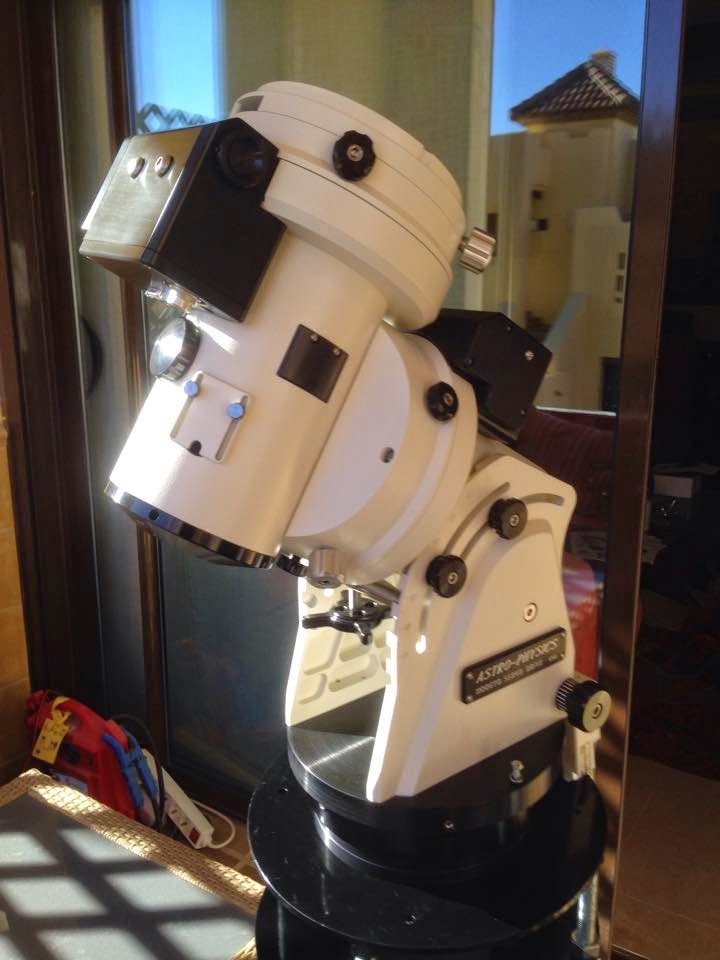


The AP mount 1100GTO is an excellent mount for precision astrophotography. This particular mount does not include the Absolute Encoders. AE are the latest technology in precision guilding.On axis encoders have many advantages, they should not be considered a panacea for taking long unguided photos. External factors such as optical tubes that bend and differential refraction that conspire to degrade pointing and tracking accuracy cannot be fixed with on axis encoders.

Advantages of on axis encoders:

1. Mount is marginally easier to use by eliminating the need to initialize the mount's position (through homing or synchronization) at start up or after power loss.

2. Provides improved pointing and tracking accuracy by continuously monitoring the position of the main gear, as opposed to an encoder mounted to the motor's drive shaft.

3. Virtually eliminates errors caused by periodic error as well as the need to train periodic error.

4. Transparent operation; the on-axis encoder hardware and electronic sensors are integral to the mount's mechanical design, control system electronics and control software.

Disadvantages of on axis encoders:

1. Cost. On axis encoder technology is expensive. Not everybody can afford it, although I am sure that everybody would like to have it. 

On,y two others mounts provide AE, 10Mircon & APA, apart from these three supplier, I am not aware of any other.


The Mount would need a pier to hold it steady and strongly fixed, I decided on a 8" diameter steel pier with a top movable flange to avoid complication when the mount is fixed on.


This is the top flange with the AP adaptor that will hold the AP mount


I also included a tray for the mount.


Finally the RAPA polar alignment scope.


The final setup with all the units assembled.


Apart from the setup, there are all the bits & pieces that will assist me to control better the mount.

The Mount Hub Pro, is an excellent addition to all mounts, it will provide just a single USB cable from the unit to the laptop. From the hub I will connect (input)at least five accessories, like;CCD, AO, Dew Heaters, gilder camera and so on. Instead of having all these units cables running from the pier to the laptop, only one output will be used from the hub.


Part 3 - Testing software to make the mount and all other units function 


This diagram comes from AP and shows the mount control panel, hardware & software connectivity 


First endeavour on the new Astro-Physics mount 1100 GTO

The alignment routine is a bit different to what I've used before on the HEQ6 and CGEM. The AP will assume perfect orthogonality within the mount itself, so if you want to use Polaris as an alignment star you need to be spot on with the OTA mounting. Best avoided with my gear I think. You will centre one star and then select star two. The mount will slew there. Unlike routines I'm used to, the AP routine expects no internal errors, but instead assumes your polar alignment is off if star two isn't on the cross hairs! So you use the alt/az adjusters to physically centre star two. A few iterations of this will have you aligned with the NCP to great accuracy. To target cone error you'll need to flip and do a routine to cancel the effects of a misaligned OTA. (I don't flip so won't bother with that until I take this one out to a dark site)
It's an absolute joy to use in short. It adjusts with no effort at all in alt and az to find Polaris. Polar alignment was extremely easy using the new RAPAS - Righ angle polar alignment scope. This has a built in diagonal, and the reticule has circles and hour markings rather than the constellations. It will make for even easier setup with less neck strain.
It slews very precisely, and I can't see any traces of backlash judging by star movements on the CCD. I didn't go through the full routine, but did a good PA and then I synced on Kochab. In theory this is all you need to do to get going - and it sure was! Any target I picked from the keypad appeared almost on the cross hairs straight away.


I set guide rate to 0.5 sidereal, on the AP Ascom V2 in Maxim DL calibrated quickly using 1 second intervals - from then on it was plain sailing! I have been used to the graph constantly going off scale with the EQ6, I've seen Dec just trail off never to return... I used to resort to high aggressiveness and max one second interval to hold it by the ear. Not so this time around!


First alignment only using a one polar alignment, then selected the first star (Kochab) and it when directly to the center of the cross-hair. This is a 10 seconds unguided.
Kaypad


Part 2 - Cabling and Power Supply


It is important that you cable correctly from the mount to the computer /Laptop, my recommendation is to use the minimum cabling from the mount to the PC, but having said this, you would need to feed not only the power supply to the mount, but also the communication /transfer of data from mount, CCD, guider camera etc.


To overcome the spaghetti of cables surrounding the mount and telescope, and avoiding many meters of cables passing through the carriers from the mount to the 'control center' I purchased a 'Mount Hub' (see above).

This became a tricky situation, First you need to place the Hub in a position that will move with the scope, camera etc, this way once you connect the cables from the units to the hub they will be kept in position. The other benefit is that only one, say cable connecting from the Hub to the Laptop is used, instead of having a minimum of four /five (camera x2, Dew heater, OA, auto focuser).

The mount cable I decided to separate from the mount hub, as i wanted that communication from it to the laptop was singular in avoid fluctuation of data.


The cables carriers/trunking will have to be water proof (in my case) to withstand the weather elements, even if the distances is not too much like in my case, it is vital that cables are probably sealed and separated from communication cables and power supply cables, this will avoid affecting with the data coming from the mount and back.


 The following images shows how you will need to separate the data to the power cables, I passed two RS232 cables, both will connect to the Astro-Physics Mount, and an extra two USB cables, one that connected to the Mount Hub Pro, the other is reserve just in case I used it.

On the power supply, I passed two 12V 6amps cables for the Mount Hub Pro, and the other one to the AP Mount. I also passed two 240V cables to supply the QSI632 CCD and another as reserve.


To have a constant power supply the best solution is that it will come from the wall socket, having batteries to supply the mount and all the other units, is not ideal given that after a few hours taking images there is a good possibility that the power will fall.

The solution I found (after searching in the net for days) was a converter unit coming from 230v to 12-15v, 7amps with 5 constant.


These two units will provide a stead power supply without interference to the units from the control center.


Permanent Pier

In the past two months I been constructing a permanent pier with the sole propose of minimize in-balancing and increase stability. Securing the pier is the most important part in the construction, having a permanent pier should give you the confidence to incorporated the mount, telescope and all its accessories including the counter weights.
The Image on the left show the amount of kilos of cement used to secure the base of the pier with 4 bolts 1 foot length with a 'L' shape incorporated inside the wet cement. I also inserted 2 tubes which later I inserted electricity cables.


The above images shows the 8" diameter steel pier already bolted down and balanced, the two tubes are inside the pier this will ensure dryness and is separated from the PC (USB) cables to avoid electromagnetic interference.


The left image shows the upper section which goes on top of the pier top flange, Its produced by Hans Pier flanges and will connecting with the pier's flange to the Astro-Physic Mount 1100GTO.


Increase resolution - How to find the FOV for the camera/scope combo


The first is to use a CCD chip with smaller pixels.  The problem here is that you are limited by what cameras are available and by financial considerations.  Also, to get a wide field of view with small pixels you need a CCD with a large number of pixels.  This means more money and more data for the computer to deal with, making for more processor-intensive image manipulation.

So, more pixels and small, but hold a minute apart from the cost there is other issues.

Relatively inexpensive CCDs typically have smaller chips, can have a  lower quantum efficiency, and lack certain features such as self-guiding and compatibility with certain accessories.  Advanced CCDs take up where the smaller camera leave off, offering larger chips and more.

If the goal of your imaging is to get pretty pictures, the number of pixels on the CCD chip can be an important factor.  More pixels means a larger image on screen and the possibility of creating larger prints.  Cameras with a large number of pixels will often have small pixel sizes, meaning the resolution is higher than a chip with large pixels, which is also often an advantage.

The advantage of larger pixels is increased sensitivity and a better match to longer focal length telescopes. 


On short focal length scopes, large pixels can produce undersampled images where the resolution is not as high as is possible.  While the disadvantage to small pixels on a long focal length scope is a decrease in sensitivity, this is more than made up for by the advantages that the sheer number of pixels provides for image processing and display. 


For example.  is the 11-million-pixel STL-11000M camera from SBIG.  This camera offers a huge field of view and tons of pixels for extremely high-resolution images

For a basic rule of thumb,

§         figure you want small pixels (13-microns or less or 0.013mm) for short-focal-length telescopes, and,


§         larger pixels (16-microns and up) for very long-focal-length scopes. 


But for pretty pictures, the rules can pretty easily be stretched.  If your goal is achieving the best resolution of reaching the faintest possible magnitudes, sampling is more critical. 


The only way to get more up close and personal is to increase the resolution of the image. The small chip gives the impression of being really zoomed in, but this is not the case. An object of size 30"x30" will always span 30x30 pixels at 1"/pix for all chips, from the webcam type to the KAI 11MP.

The properties that define the resolution are...pixel size and focal length. The relation here is for pixel size in microns (micrometers) and focal length in mm.

arcsec/pix= pixel size/focal length * 206


For a Sony ICX285 type chip found in the Atik16HR, QHY??? and SXV H9 the pixel size is 6.45um (microns), and asuming a focal length of 780mm, this corresponds to 1.73"/pix.


Arcsec/pixels =(6.45 /780)*206 = 1.7”/pix


To find the FOV for the camera/scope combo,


Multiply this by the number of pixels in the horizontal and vertical directions. For the case of the ICX285 (1392X1040), the field of view is 40'X30'.


FOV = 1.7 x (1392 x 1040)  = 1.7 x 1392/60 = 39.44

                                              = 1.7 x 1040/60 = 29.47


FOV = 40’x30’


The ICX285 type is a good chip...very sensitive and has low dark current.
 answer to the framing of M51
angular diameter is 11x7 arc-minutes...therefore the camera FOV with the telescope 780mm long will produce a 40’ x 30’ which is well over the M51 diameter.


If this is too small a sensor, you could try the KAI 4021/4022 sensor. Due to its design it has a lower sensitivity and higher dark current. it has 7.4um pixels and a 2048x2048 sensor. Starlight express use this chip in the H16 camera.

Or if you are feeling wealthy, the KAF3200ME is incredibly sensitive...around 0.75 at Ha (656nm). it is a 3.2MP sensor with 6.8um pixels. However, it doesnt feature an antiblooming structure so bright stars will bloom during an exposure.

A camera can have an arbritary size of pixel (almost) usually from 5-24um and any number of them usually from 700x500 to 4096x4096...so small chip doesnt mean zoom...resolution means zoom. The size of the sensor only dictates the field of view.

Maxpoint Plate Solving

MaxPoint is one of the two softwares that I've heard of written for this job. TPoint being the other and as far as I'm told much better too. Since I already had full version of Maxpoint installed I fired it up to see what the go 'to' is... :)


The MaxPoint becomes the telescope hub so it can intercept any goto commands from apps such as planetarium TheSkyX, to transparently apply pointing corrections. I figured that I need to disable the alignment corrections in the EQMOD for this to be effective, but not quite sure about it yet.

Only requiring minimal setup, I kicked it off with a 25 star calibration routine, wasn't game enough to go for the default 100 stars!? I can see this is really written for permanent observatories with high grade mounts. My poor little EQ6 would probably overheat after 100 continuous slews.
 
Each slew followed by plate solve started to populate Calibration Observations table with calculated pointing errors. It also put little red 'X's on Sky Map representing the points its visited in the sky. I actually enjoyed sitting back and watching this whole process unfold before me. My polar alignment must have be good as all 25 slews yielded successful plate solves. So, I might actually give the 100 star calibration a go next time at the risk of my mount melting down. 

I am using these screen shoot from Maim DL webpage to show the process in each stage.


Scope Setup configures MaxPoint for your telescope. All settings in this dialog box are extremely important for accurate telescope modelling 


I can see that it has worked out my polar alignment accuracy as well and I might try its built-in Polar Align feature next time. I haven't gone into working out what the other figures exactly mean yet but test slews to targets in different parts of the sky definitely showed improvement over the EQMOD's modelling, but still it didn't put the targets dead centre. May be it needs a 100 star calibration or it may be that I'm expecting too much from my poor little EQ6. Well, for now, plate solving and re-slew technique works well for my portable setup and may look at  Maxpoint or TPoint again later on for a permanent setup, perhaps with my new AP mount arriving around in Dec 2014 I will use the 100 target.
 
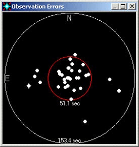
At the end of the scope dancing routine, below window shows a summary of  the calculated errors contributing to my pointing accuracy.