Sync Refines OFF → A 2s ENTER press with object
data displayed will SYNC the model on the object coordinates.
Sync Refines ON → A 2s ENTER press with object
data displayed will ADD A POINT to the current model, with the object
coordinates matched against the encoder readouts. 10micron
official ASCOM driver settings meaning
Enable Sync OFF(KeyPad-PC)→ All synchronization commands through the driver are disabled, so the
model cannot be altered. Basically
cannot be used for modelling externally.
Enable Sync ON (Keypad), Use Sync as Refine OFF(in setup PC) → The ASCOM synchronization
command will SYNC the model on the given target coordinates.
Enable Sync ON,Use Sync as Refine ON→ The ASCOM synchronization
command will ADD A POINT to the current model, with the given target
coordinates matched against the encoder readouts. (basically will allow model
points to the model already model) Per Frejvall's ASCOM driver settings
Sync behaviour "Syncs append to refine model" →
The ASCOM synchronization command will
ADD A POINT to the current model, with the given target coordinates matched
against the encoder readouts.
Sync behaviour "Syncs align model" →
The ASCOM synchronization command will SYNC the model on the given target coordinates.
Which
settings should I use?
When building a model with the keypad, you will use the 2-Stars or
3-Stars alignment and Refine Stars functions. These works the same whatever the
settings are, so don't worry about them.
1.Using the HandPad do a 3-Stars alignment
2.Using the HP do a Polar Alignment.
3.Using the HP/PC do a new 3-Stars Alignment (given
that after the polar Alignment the previous 3-Stars alignment will disappear)
4.Using the HP/PC do 15 to 20 Refine Stars Alignment.
5.Using the HP/PC save this model.
When building a model with a model
building software such as Model Creator, Model Maker, Mount Wizzard,
6.Normally you'll set "Enable Sync ON"and "Use Sync as Refine ON"on the 10micron ASCOM driver,
7.or "Syncs append to refine model" on Per Frejvall's ASCOM driver.
In normal operation, usually you shouldn't resynchronize the model.If you connect to the mount with the 10micron ASCOM driver, you can
prevent any synchronization through the driver by unchecking "Enable
Sync" in the driver setting (note: this won't disable synchronization with
the keypad, or with other software that connects to the mount with another
driver).
If you have really to synchronize the model on a single star/object (please
read above before deciding to do it), you can do it with the keypad (point at
the object, centre it with the keypad, then, leaving the object data displayed,
press ENTER for at least 2 seconds). In this case you must have "Sync
Refines OFF" in the keypad.
If you want to synchronize the model on a single star/object (again - please
read above before deciding to do it) with an external software via ASCOM, check
"Enable Sync" and uncheck "Use Sync as Refine" in the
10micron driver, or set "Syncs align model" in Per Frejvall's driver. Why synchronization fails?
Usually, the mount won't accept a synchronization or a refinement point if the
coordinates that you are trying to synchronize are too far away from the
coordinates the mount is believing it is pointing at. The exception is for QCI
mounts before the alignment, which accept almost any synchronization except for
positions near the meridian, where there is ambiguity on whether the telescope
is west or east of the tripod - these positions can be pointed at with two
different mechanical configurations. If you encounter such a situation,
probably there is something wrong with your model - check that the right
ascension axis is pointing at the celestial pole, that the clock is at correct
(including timezone and daylight saving), that the site coordinates are
correct, that the telescope is mounted in the correct position on the
declination flange.
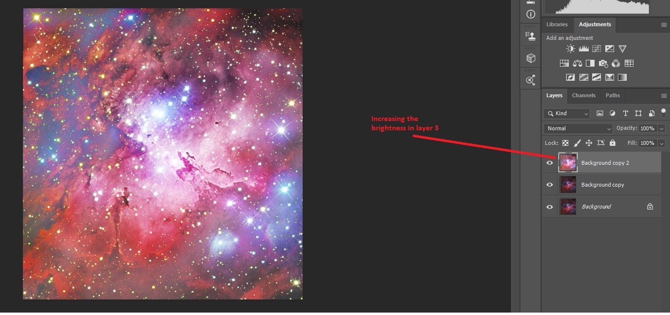
Masking is an ideal tool in Photoshop used for astrophotography. I am using an image from M16 to show how we use Layers with Mask to improve the center of the nebular.
First Step create two more copies of the image /2 new layers
Step 2 , using the 2nd layer we going to apply curves to brighten the center of the nebular
After bright the center we use this image to 'merger down' to the layer, use the right click of the mouse to bring-in the options , you find there the 'Merger Down 'option. See below the result.
Step 3 , we are using Layers Mask-followed by Reveal all in the Layer folder, the using the brush tool and having the square 'black' on.
Step 4, we brush the center to darken this area only
Step 5 go to Filter-Blur-Gaussian- around 40 to 45 level will be fine, then 'Merge down' again
Here comes the most complicated part, you will need to curve again the copy layer to brighten all.
Do two more layers again (now you have four). See Below.
Step 6 darken areas in the image to make it more dramatic using again the mask brush, then Gaussian it again, when using the gaussian it a personal thing to what shadow /brightness you prefer, this I leave to you. Finally Merge down and Flatten all.
Save it
Final Result
New Mount: 10Micron GM1000 - First Time Testing
With everything in place, I could finally take the mount out for the first
time after a very long wait cause by moving house to a better viewing location.
First, I wanted to try out the rough polar alignment with the green laser
pointer on the scope,
Although the laser light was weak, but I could see a beam weak but
noticeable to align the beam
to the North Star.
The 10Micron mount uses simple star alignments for polar alignment (3
stars for a rough alignment, a full model -20 at least for exact polar alignment), always using the hand control to select the stars , DO NOT use at this stage Model Makers or Model Creator.
One point, try to center the Polar Star with a view scope or Computer program like Maxim DL before you start any alignment, if not it will give you headaches. When the mount is not
even nearly polar aligned it is difficult through a camera to center a star when it comes to the 3 or 2 star alignment, you will have to use your HC and view-scope to slew near the star.
Before polar alignment, I tried various of the 10Micron functions:
1. Balance check
The
mount moves the scope into specific positions and measures on both sides if any creates more or less
friction. Measuring in RA was quick and showed that I was only 0.00% off (everything below 0.04% is
considered enough for good, stable imaging). For the DEC measurement, it was a bit of by 0.02, I measured the level with a bubble level and it was good, I then moved the weights lightly down measure it again and it was spot on.
2. Orthogonality (cone error)
From the various alignment points, the mount calculates the orthogonality
error. In my case it was it was out by 12' 00", I realized that the mount bubble level was not dead center, I centered it by lefting of the tripot legs. Did another test and the Orthogonality error was reduced to 2' 45". Honestly I am not sure if this is within the parameters allowed.
3. The 3 Stars Alignment (prior Polar Alignment)
People say that the polar alignment was fairly easy, NOT TRUTH. But before a polar alignment its recommended that you do first a 3 star alignment, you do this 3-star alignment from the mount Hand Control the 3 star alignment can be achieved relatively easy if you have certain things done prior.
Balancing
Orthogonality
Rough but relatively pointing to the star
Correct UTC /Computer time
GPS or manually input the correct location.
If you have the above correctly input into the mount database then when slewing to the first star the mount position will be very near.
At this stage DO NOT GO TO Polar Alignment yet. The next step is to add more stars after you finish the 3 star alignment (10 is enough) to the pointing model of the mount through the Hand Control.
4. Polar Alignment
Now is a good time to polar-align.
Pick the Polar Align procedure from the keypad and pick a star from a list. I picked one near the meridian and fairly close to the equator. This time you must not use the hand-pad to center the star, but use the mount alt/az adjustment knobs to do the centering. Press enter when done. That’s very nearly it - but not quite as the pointing model is not that accurate as you moved the mount physically with the adjustments, but not far off. So next step is do another 3 stars alignment.
From the keypad select 2-Star Refine and pick a star from the list, the GM1000 will slew to it, halt and beep when ready and you center the star in the reticule eyepiece or the PC Screen (I use Maxim DL) continue shooting frames (every second) and center the star.
Keep doing this in the 'Refine' to build up say a 12 to 20 star model from stars spaced widely over the sky - you can build a max of 100 stars into your model which is more practical to do (time wise) in a permanent setup. After each additional star you are told what the RMS pointing error is, is everything is working well the RMS will reduce a bit with each Refine star centered.
I experimented in three nights to learn how best to do it and how fast it could be done and how good the results are and if further model building and polar alignment iterations improved things. I performed
The optimum solution trading time for accuracy was to 3-star align, then add stars to build at least a 20 star model in the HC/ mount software.
Polar align.
Then repeat the 3 star align a second time and again go for at least 20 all-over-the-sky stars.
Polar align a second time.
Finally finish off with a third 3 star align and 12+ "star refine" to build a final model.
I tested the un-guiding without being totally accurate (with an 11 RMS) and unguided with a 900 sec image with prefect round stars. (see below)
5. Tracking precision
Without guiding, I measured the precision of the mount
as-is (i.e. no model or such): << 1" !!!
That's a pretty awesome precision!!!
900 sec test - Right in the center
You can notice on the Hand Control screen the information about the Polar Alignment, the RMS is 11", actually the following night I managed even a low one at 7" RMS, with 12" Polar Alignment error. The screen also shows the scope Orth Errors which is at 2'.
UTC-Local Time setting confusion
There is always confusion when setting up your mount time it needs to be synchronized with your computer and astronomical software like maxim dl, SGP or TheSkyx among anothers.
I am using 10Micron 1000 mount , and the hand control is simple if you LOOK well at the meaning of the screen when setting the UTC time with your local time.
In the HC go to Menu -Local Data , remember what i said pay attention to the words 'Local Data' meaning the condition of your local time, for example
In South of Spain we have the following:
Summer Time (+1) on
UTC +1
Local Time (currently as I write this 16:38
So, in my PC I have the correct time (Window 10 right hand corner) 16:38
In my HC I continue with the setting, Menu-Local Data-Clock
Select 'Date and Time' and SETUP your local time. NOT the UTC time
Then select 'Local Timezone' in other words your region UTC difference to your Local Time, in my case is +1
Finally select 'Daylight' or Summer time save. In my region is 'ON'
To check if both Computer and Mount are correctly setup go to Maxim DL, under Observatory select 'site and optics'
Under Universal Time you should have Computer 15:38 and Telescope(which is mount) 15:38.
THIS IS THE WAY TO HAVE ALL THE TIME CORRECT IN ALL THE SYSTEMS.
IT WORKS THE SAME TO ALL DIFFERENT MOUNTS IN THE MARKET.
Different Time Definitions
UTC ("Universal Time Coordinated") is a time scale derived from TAI but adjusted with leap seconds in coordination (thus the "c") with UT1. In other words, UTC is designed to keep an, essentially, unvarying atomic time scale (TAI ) relevant to an imperfectly rotating Earth (measured by UT1).
TAI ("International Atomic Time") is a time scale based on an international ensemble of atomic clocks.
UT1 ("Universal Time One") is an astronomy-based time scale traditionally derived by combining UT0 observations collected from worldwide locations.
UT0 (“Universal Time Zero”) is a geographically local, astronomically measured, time scale.
GMT ("Greenwich Mean Time") is a version of UT0 as traditionally measured from Greenwich, England. Leap seconds are irrelevant to true GMT because GMT is astronomically derived.
GPS Time is an atomic-based time scale maintained by the U.S. Naval Observatory. Commonly, GPS receivers convert "GPS Time" to UTC by means of additional information encoded in the signal stream.
Culturally:
UTC is the modern equivalent of GMT in that it presents a worldwide and not-seasonally-changing time stream. They are encoded in the same format.
UTC and GMT differ by, practically, nothing. Moreover, many organizations, such as the BBC, which claim to report GMT are actually reporting time derived from an encoded radio or GPS source. In other words, they report UTC - sometimes even UTC derived from GPS Time.
Pixinsight-Part 1 (Blink & SubFrame)
After using Photoshop for some years I always had this urge to try Pixinsight, as I always say, you learn something new everyday, and who knows I might develop my processing and advance further, I am not sure where I am going or what I will achieve, but whatever I lean or not I will recorded each step on the way.
When I open SI and I see all the different processing tools under 'All Process' and those under 'Scrip' and the first impression is wow, where do I start??, while in Photoshop, the frames are coming over already calibrated (from third party software like PhotoStack2), in SI you have the option to do the calibration as well, or used a third party software to carryout this task and just concentrate on the processing the frame in PI, so this addition of extra menus its a bit intimating.
.
First before I start this adventure I will start off by describing the meaning of 'Image Scale' followed by some useful points about PI , why?, because this awareness will come handy later.
Is the angular area of each pixel can see, this is referred as 1 bin, so if we combine 4 pixels into a single pixel the are will increase by 4x = 2bin.
First Setup
A camera / telescope combination. Telescope with 106mm aperture and 530 focal length, this means a F5 (530/106). The camera chip 2750 x 2200 with 4.54 pixel size. The image scale of the pixel is 1.76 arcsecond/pixel and the field of view is of 80.98 x 64.79 arcmin
Second Setup
Telescope 356mm FL is 2563mm therefore F7.2 will result of an Image Scale of 0.72 arcsec/pixel and Field of View of 48 x 33 arcmin with an FOV in degrees of 0.8.
So the best resolution of both combo is the latter with a 0.72 arcsec/pixel
2. Loading an Image
When loading an image in PI in 32 bits, the computer will display it in 8 bits, do not reduce from 32bits to 8bit the images. Instead use the STF (Screen Transfer Function) to stretch the images to see it better on the computer screen.
3. PI is divided into two main sections for processing.
On one side we have the Process and on the other the Scrip. In Process you can find all the tools provided by PI, and in Scrip are third parties software within PI developed by PI users.
4. On the top screen modules/menus
On the top selections we have : File-Edit-View-Preview-Mask-Process-Script-Workspace-Window-Resources and if you scroll down there are quite a bit of extra menus.
We will skip these menus for now.
5. Inside PI (whole) The software is divided into 4 sections - Preprocessing, Linear Post Preprocessing, Nonlinear Post-processing and Special Processing
Part 1
Pre-Processing
The processing of an image can be achieved by using the processing tools, if you click on the 'Process' and then <all process> you will open the screen below.
After a night of imaging you are exacting but also aware that not all the frames would be use for calibration for different reasons, previewing them can be achieved in PixInsight. Most processes can take quite a bit of trial and error to get the right settings and fine tune them for the optimal result. We run these processes on previews so that it is much faster to see the effects compared to running it on the complete picture. Furthermore, we can use multiple copies of the same preview and apply the process with different settings so we can really compare the results of our fine tuning in great detail.
One of tools that unable preview your frames is 'Blink', it will preview a set of images. Open the images with the small folder in the Blink dialog window.
This tool will be part my of image-processing workflow, which lets me inspect each image and discard any that appear to
be of poor quality (images with clouds, poor tracking, and so on). PixInsight’s
SubframeSelector script (Script > Batch Processing > SubframeSelector)
can automatically evaluate images and sort them into “approved” or “rejected”
groups using quality criteria you can modify. When evaluating image quality, I will use this opportunity to identify the best one to use as a reference when
aligning images.
Preselection frames
1. Open the Blink tool
in the Process Explorer (vertical tabs);
2. Select the light
subs in the Blink tool;
3. Press the "play"
button and check if you see streaks of satellites, planes or meteorites;
4. If stripe formation is
visible, it is usually located in one subframe, write down the name of the sub
in order to have it removed in the subsequent steps or remove all the file
physically by
removing the 'X' to mark it as bad.
5. Its important that you keep those good-looking images and have adequate number of good images.
6. Thinking about those poor images, I believe it will be a good idea to create a new folder (give it a name that you know they junk images).
The following Video will help you to understand better the process
SubframeSelector script
After calibrating we could immediately
jump to registration (aligning the images). However, there’s another tool
in the PixInsight called SubframeSelector that can help to enhance your
results if we use it before registering our data. The
originatly the SubframeSelector was to identify light frames that
might have errors that were severe enough to exclude
them in your final stack. This could be from a cloud passing through the
field of view, a piece of grit sticking in your gears and throwing off your
tracking, focus slipping, etc. It also supports the ability to add a
keyword into the FITs header that can be used by ImageIntegration later on to
weight how the images are combined (but this is another story). This is exceptionally useful if you
have data from multiple sessions or instruments where the SNR or resolution my
vary considerably due again to the elements mentioned above. By weighting images you can control how much influence
an sub frame with a lower SNR has on the final integrated image.
First step is to select the images then move to opening it inside SFS (see below), Under System Parameters, enter the image scale
of your telescope (use the formula I mentioned above) and camera in arcseconds per pixel and other pertinent
information.
If your are setting the Star Detection and Fitting and these settings are inadequate, the console will report
failure, leave the setting as default it works perfectly, but before hitting the measure button, if you feel that you can enter a formula into Expressions/Approval to automate the grading
process, do so, if not do not worry. Finally click measure, and the Process Console will appear as the script does its
calculations.
Tables
The Table at the bottom , shows the finding calculation Note, you can change the field of
interest, three of the main and basically used by many astrophotography are: the images’ signal to noise ratios
, choose SNRWeight (noise), and in descending, if the SNR reading is higher-this is a good thing. If your choose on the Full Width at Half Maximum (FWHM) of the stars in the images, remember if the file at the top of the list would have the
highest FWHM value—this is a bad thing. You might therefore switch to ascending order,
placing the file with the smallest/best FWHM on top to make that category
easier to read.
FWHM measures star size/spread whereas eccentricity
measures shape in terms of how out of round the star are.
Formula into Expressions/Approval
Limits -Minimum and Maximum settings
Eccentricity
For
eccentricity <=0.4 is considered 'round', if anything from 0.4 to 0.49 will be acceptable, if generally stack anything <0.55 and above 0.55 and start to get picky and choose, it all depends how many frames you have to play with. For example if they're mostly
0.4 to 0.5 you can select with assurance and toss away any outliers that are above
that, I would reject
anything above 0.6.
FWHM
FWHM
is a lot harder to be so absolute about, as it largely a factor of the seeing. On a really good night a seeing <3", but a 5" is considered poor. As
such, for FWHM I tend to work in relative terms within the available frames I
have for a target rather than absolutes. FWHMSigma is a good approval term to
use for this and I'll typical approve frames that lie within 2 sigma, so an
approval term of FWHMSigma < 2.
To sum up a typical approval expression I'll use for these factors in SubframeSelector will be:
Eccentricity < 0.5 && FWHMSigma < 2
[What I am saying here is I will only accept those frames with FWHS that lies with 2" and Eccentricity with a 0.5 value or below, any frame above any of these two parameters will be automatically rejected.]
Smaller FWHM values are better. I’ve also restricted the
list by the Eccentricity and Noise metrics.
Noise is fairly straight
forward, the higher the noise level the more difficult it is to discern your
target, so again, lower values are better.
Eccentricity is a measure of
how far from round a star is. If a star is very elongated it will have a
higher Eccentricity value, so it is also better to have lower values here.
The
weighting is more complicated. Basically its means that you need to use one of the three weighting (SNR-FWHM or ECCEN). When applying the weighting to one of the three,
first it will be based upon it own parameters--if you use FWHM as your most
important factor to build the expression. If Eccentricity is more important to you than FWHM you can
change the weightings in the formula. If we take the expression below (provided by....) and we take my reading below under FWHM its ranges from 3.05 to 3.6, so I want to use a maximum value of 3.05 (<3.05) not further then this, so I put in the first part of the expression (3.6-3.05). For the Eccentricity range 0.534 to 0.511, and for the Noise its 0.736 to 0.707.
The numbers in front of each factor is based on 50 (50 frames), if you are interested in having a good FWHM (better resolution to rounded stars) you will have a higher value (30) in front of the equation. This is what the 30, 5 & 15 values are for. If you were less concerned with resolution and wanted rounder stars with a better SNR then you might weight FWHM lower and Eccentricity and Noise higher. Most important Second most important lease important
(30*(1-(3.6-3.05)/(3.60-3.05)) +
5*(1-(0.534-0.511)/(0.534-0.511)) +
15*(1-(0.736-0.707)/(0.736-0.707))) This expression will be reduced to:
(30x(1-(1))+5x(1-(1))+15x(1-(1)) = 30+5+15=50
If you need a spreadsheet to help you out in the expression, I found this easy way out to expressions in the following website: Expressions formula in Excel (click here)
Preprocessing Flow
When preprocessing images, we follow a subset of these steps
(depending on the reqirements of the data):
1.Image
Calibration (use Pixinsight’s ImageCalibration process to apply super bias,
master dark and master flat; perform RBI mitigation if necessary)
2.Blink
Selection (use PixInsight’s Blink process to quickly identify and eliminate out
of focus, low contrast, or otherwise poor frames; this is also a good time to
review the effectiveness of calibration on each sub)
3.Cosmetic
Correction (use Pixinsight’s CosmeticCorrection process to remove hot pixels,
cold pixels and defective sensor columns)
4.Subframe
Selection (use PixInsight’s SubframeSelector script to measure quality of each
sub, eliminate outliers, and apply a quality weighting value to each sub based
on FWHM, Eccentricity and SNRWeight factors; also to note the highest quality
sub for each filter for use during local normalization)
5.Image
Registration (use PixInsight’s StarAlignment process, including drizzle data if
desired)
6.Local
Normalization (use PixInsight’s LocalNormalization process for including
localized contrast data; improves signal to noise ratio and results in cleaner
background transitions after integration)
7.Image
Integration (use PixInsight’s ImageIntegration process, applying quality
weighting and local normalization data from earlier steps, and updating drizzle
data if desired)
8.Drizzle
Integration (use PixInsight’s DrizzleIntegration process if desired, applying
local normalization data from earlier steps)
9.Dynamic
Crop (remove any black edges due to tracking movement during imaging; applies
an exact duplicate crop to each of our stacks so that our registration remains
intact)
For anyone looking for image capture software -
SGP is one great package, although for me CCDAP still my favorite, its compatible
with TheSkyX, and Maxim DL making it a excellent imaging capture team difficult
to beat, true you need to spend good money compare to SGP.
SGP has developed over
the past couple of years, easy to use and for a beginner you can developed your
skills using it as it has grown. (The developers are very active on the forum -
answering questions and taking suggestions on board).
SGP like CCDAP is compatible with other astronomy
software like PHD2 for guiding (if you need to guide), with Astromi for Model-Creator
or Model Maker for modelling the sky and MBox for GPS and temperature control, all excellent
software that works perfectly with 10Micron mounts, a mount which is top in my
list for amateur astrophotographers.
The mount of course needs good polar alignment as
always but I do not have to align on any stars - plate solving tells the scope
exactly where it is pointing. When it reaches the meridian - the scope will
flip guided by this software and resume on the other side without any input
from me at the time of flip. It works in tandem with PHD2 guiding software and as
well as when not using guiding scope only with the sky modelling.
I recommend
this combination for anyone wanting to control your astro-image capturing, I
have mentioned above the mountl, It also controls the camera (obviously) and
the filter wheel (if used) along with the focuser (again if you have a PC
controllable set-up)......along with a couple of other things.
I don,t think you can go
wrong with SGP for the money, like you can't go wrong with Pixinsight or PS for
post processing for the money you pay for them. You should buy software and
learn to use it and resist the temptation to buy something
"else" unless there is a specific capability that you cannot get with
what you already have - say "mutliple targets". Knowing how a package
works will outweigh anything else over time, and it's for this reason that I prefer CCDAP over
SGP.
I
use MaximDL all the time without serious problems. In last years I have had
exactly few problem that had me flummoxed and cost me imaging time, but what program
is free from it.
I've used CCDAP, MDL with TheSkyX it with a 250 Tak and the 106ed, It works fine with my SX694 and FLI16 and the
Moravian 11000, my 10Micron Mount, my AP 11000. It gives me a vast array of
different capabilities to examine the data I am collecting, QA it, stack it and
due on the fly digital development. It handles meridian flips, has auto
shutdown capabilities, etc etec. I have NEVER seen a "guide star"
problem when the guide star was present in the sub frame. I have seen hot pixels
a lot though and very few people who understand how to handle them. It could use
better hot pixel detection for the MDL.